|
|
Post by tfoley45 on Dec 16, 2023 8:19:04 GMT -5
Good morning :
My handle is tfoley 45 the 45 is / FP 45this my first time here. still learning,
im not running a layout, no room. But i like what other creative people are doing with their hobbies.
My current project is a complete headlight number board class light display
for my dads railroad collection I am doing a MP 15 front
|
|
|
|
Post by icghogger on Dec 16, 2023 8:43:22 GMT -5
Welcome to our forum, and please share your work with us when you can!
|
|
EMDX6043
Chairman
Future ex-modeler
Posts: 837
|
Post by EMDX6043 on Dec 16, 2023 14:43:24 GMT -5
Welcome to the forum!
|
|
|
|
Post by big train james on Dec 18, 2023 20:24:07 GMT -5
tfoley45, There is an EMD specification sheet for the mp15ac located on the UtahRail website. The brochure includes line drawings of an mp15dc, with major dimensions noted. The dimensions for the headlight and numberboard cluster itself are not indicated, but they could be derived based on other dimensions that are shown. That will at least get you the size and shape of the carbody. utahrails.net/loconotes/emd_mp15ac_specs.pdfThe loco specs are found under Locomotive Notes/Emd Specifications. If you need info on the headlight, numberboards, or class lights, look at the 310 and 311 series catalogs found in the other thread you posted to. You can find drawings of class lights and the headlight fixture in section 5900 of the 310 catalog, and the numberboard inserts are described in section 2415. Remember that the numberboard sizes as specified in the catalog include the glass bite that fits into the gasket, so the visible part of the insert will be smaller than the overall size. Hope that helps. I'm pretty familiar with the sw1500's, haven't gotten in as deep with the mp series switchers yet. But a lot of the details translate, so ask questions if you have them and I may be able to answer. Jim
|
|
|
|
new member
Dec 25, 2023 14:11:48 GMT -5
via mobile
Post by countryroads on Dec 25, 2023 14:11:48 GMT -5
Welcome to the DD hope to see some of your work
Trying to get some of mine posted just to find the time
|
|
|
|
Post by tfoley45 on Dec 26, 2023 17:16:02 GMT -5
tfoley45 , There is an EMD specification sheet for the mp15ac located on the UtahRail website. The brochure includes line drawings of an mp15dc, with major dimensions noted. The dimensions for the headlight and numberboard cluster itself are not indicated, but they could be derived based on other dimensions that are shown. That will at least get you the size and shape of the carbody. utahrails.net/loconotes/emd_mp15ac_specs.pdfThe loco specs are found under Locomotive Notes/Emd Specifications. If you need info on the headlight, numberboards, or class lights, look at the 310 and 311 series catalogs found in the other thread you posted to. You can find drawings of class lights and the headlight fixture in section 5900 of the 310 catalog, and the numberboard inserts are described in section 2415. Remember that the numberboard sizes as specified in the catalog include the glass bite that fits into the gasket, so the visible part of the insert will be smaller than the overall size. Hope that helps. I'm pretty familiar with the sw1500's, haven't gotten in as deep with the mp series switchers yet. But a lot of the details translate, so ask questions if you have them and I may be able to answer. Jim |
|
|
|
Post by tfoley45 on Dec 26, 2023 17:32:08 GMT -5
thank you Jim !
I downloaded that before i foud this website, I have enginering drawings that my dad left me , booklet form spec drawings
i do have 1 number board and made a copy already i ordered 1 class light lens and will order the 2nd one and the headlight frame in jan my big question is do they show the spacing between head light number board and class light ?
|
|
|
|
Post by big train james on Dec 27, 2023 21:41:30 GMT -5
Interestingly, none of the reference documents I have on hand show units with class lights. They only show the headlight and the flanking numberboards. However, it's easy enough to figure out the location of the class lights from photos, and I'm in the process of doing that now.
I think it would be good to clarify what road you are trying to recreate. If it's by any chance SP, then the numberboard housing and all associated lights are quite different. I presume you are doing a non-SP road though, or else you wouldn't need numberboards at all and you haven't mentioned the gyralight and emergency light.
Even on a normal numberboard, the way the class lights were implemented varies by road. I'm starting to wonder if a lot of locomotives had class lights installed after delivery. There are a lot of photos of units without any class light openings, and they also aren't plated over. I'm sure somewhere there are examples of units with class lights removed and the openings carefully filled in with a flush welded in place blank, which was dressed and finished to the point you wouldn't know it had been there. But I bet that's a rare occurrence, with it being much more common to see welded or screwed blanks overlapping the opening, sitting on the face of the hood.
Knowing a specific road, or even better a specific road number, would also influence how the class light is mounted to the housing. Some lights were held in place with only a gasket, and no screws, in the same manner as the numberboards. The other application is to use a flat gasket behind the mounting flange, with four screws attaching the fixture to the face of the housing. The fixture is the same either way, but the hole in the housing sheet metal will be smaller for the screwed in place solution.
Anyway, blah blah blah, give me some time this evening to sort out the housing size and fixture locations and I'll get something to you.
Jim
|
|
|
|
Post by tfoley45 on Dec 28, 2023 9:52:30 GMT -5
it is the milwaukee road . the milwaukee roader mag which I HAD ! and lost! showed a real good photo of them as delivered.
What really gripes me now I worked for them in 1979-19980 in the diesel house and could have had 100s of photos of fms f units geeps7s 9 sw 1s 1500 u boats ect i can still kick myself
|
|
|
|
Post by tfoley45 on Dec 28, 2023 9:55:20 GMT -5
I do have a clear outer lens coming today
|
|
|
|
Post by big train james on Dec 29, 2023 12:45:47 GMT -5
Plenty of photos online showing the MILW mp15ac's, including some good photos of the front end. The one's I've looked at show the screw-attached class light fixture, as opposed to the gasket mounted type. That will affect the size of the opening in the housing, but not the location.
I've been trying to draw up the numberboard housing based on information I have for the sw1500. I needed to do the standard arrangement anyway, since the SP version I have done already is quite a bit different and not really applicable.
I'm getting close, there are a few things to tweak and reconcile yet. But once done I can provide the housing size and fixture locations. I may even be able to provide a pattern for the sheet metal top of the housing, since the shape is tricky at the outer ends as it tapers and rolls over from the top to side. I'll have to see if my program can figure that out.
Stay tuned.
Jim
|
|
|
|
Post by tfoley45 on Dec 29, 2023 14:08:51 GMT -5
thank you we can compare how yours work comaped to blowing up the blue print to size
|
|
|
|
Post by big train james on Jan 4, 2024 23:51:21 GMT -5
This is what I've come up with for the sw1500/mp15dc/mp15ac standard numberboard housing and light arrangement. For the most part, the housing was developed from EMD drawings. I'm pretty confident in the overall size and shape for the housing, and I'm also confident in the headlight and class light fixtures. Those were developed from a prototype fixture for the headlight and EMD drawings/catalog pages for the class light. The result was checked against various prototype photos that I could find, and everything seems to jibe. The two areas of concern are the size of the number inserts and the gasket associated with them, and the exact location of the class lights. I scaled the sheet metal openings for the number inserts from the EMD drawings, but that only yields a certain level of precision. I have a size for the inserts from the EMD parts catalog, so I'm comfortable with that. The piece of information I'm lacking is the size of the gasket, and more specifically the gap between the insert and the adjacent sheet metal. Comparing the insert size to size of the sheet metal opening, that gap appears to be 3/16". That seems too narrow given some of the other information I have, but I have no way to verify it. Secondly, none of the drawings I have of the housing include openings for the class lights. So I've positioned them based on what I see in photos. I spaced them horizontally from the outboard end of the number inserts based on photos, and vertically put them on the same center line as the number inserts. Again, I have no way to verify those assumptions at the moment, but they do look right. You said that you were going to use actual parts for the build, perhaps you can verify some of the missing information once you have them in hand. In the meantime, I plan to provide the center lines of openings as I have drawn them, and you can adjust the sheet metal openings based on the actual parts. I'm going to try to insert images. It's always an adventure when you don't do it often enough to remember from the last time.  Got it the first time.....I should buy lotto tickets.   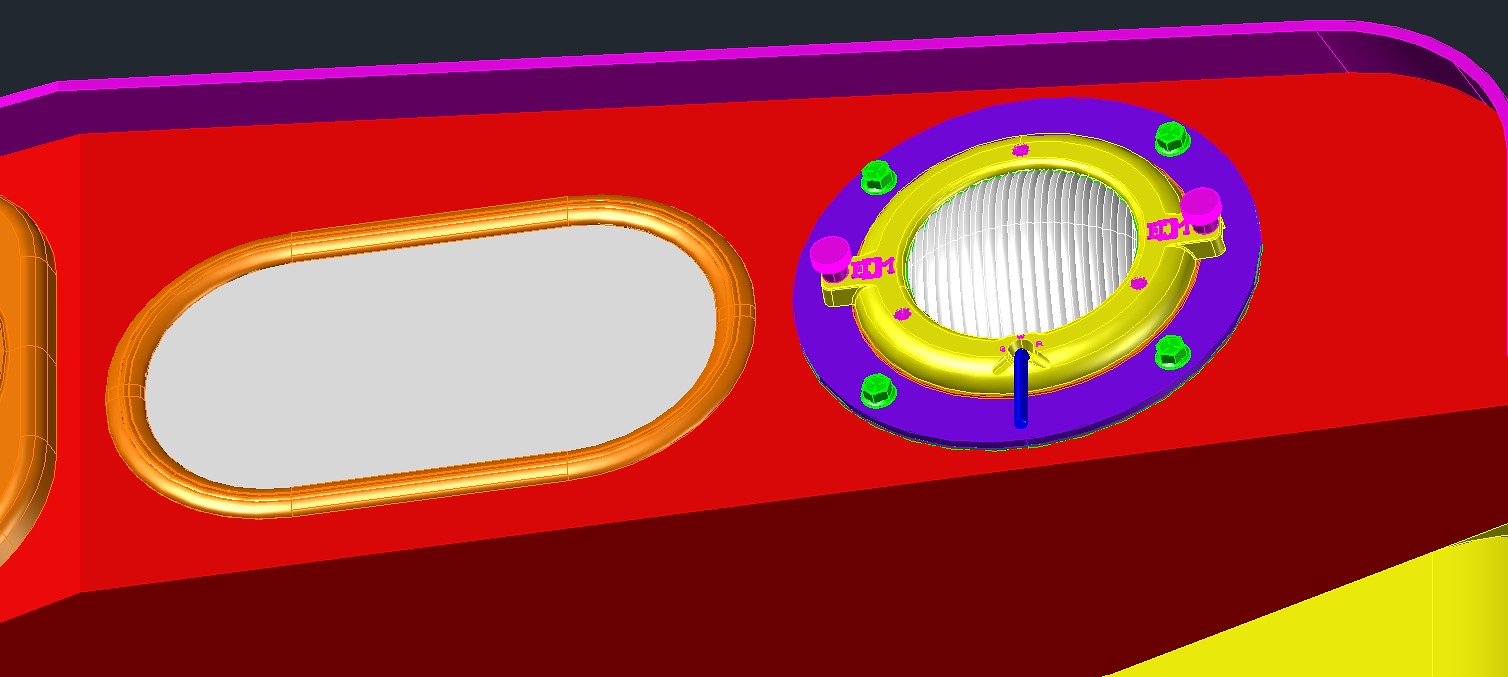 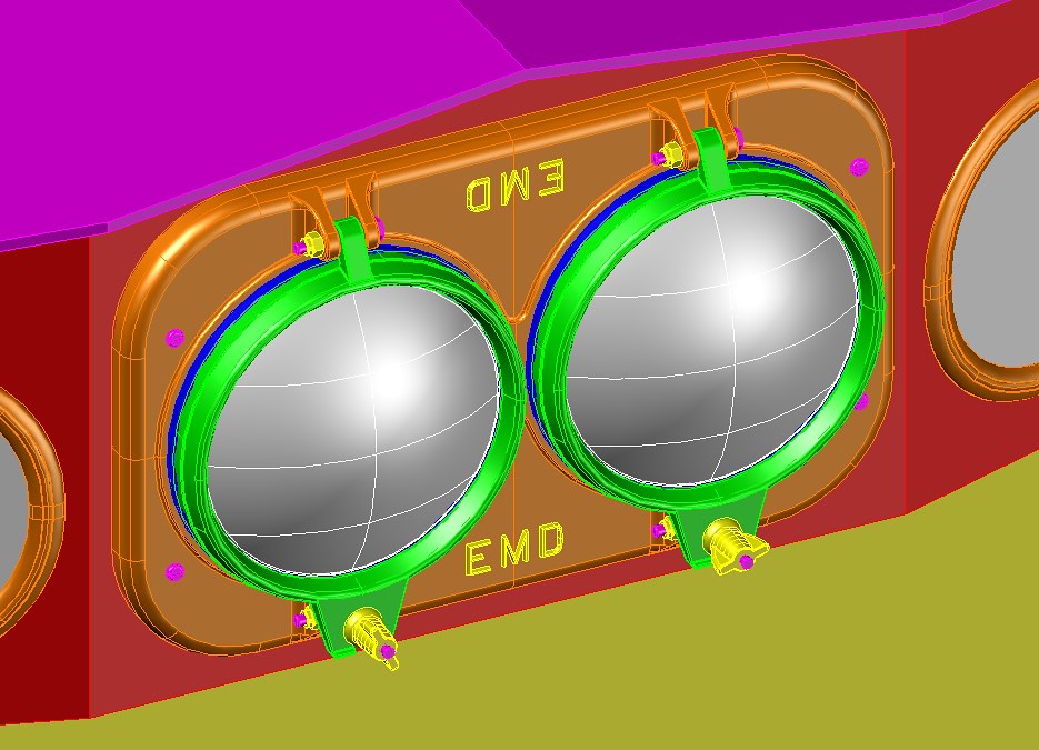 I see in the captures that I didn't radius the bottom edge of the housing. I'll need to correct that. I'm still working on a couple of drawings with the dimensions. I should have them added tomorrow or Saturday. Jim |
|
|
|
Post by icghogger on Jan 5, 2024 8:16:06 GMT -5
Excellent rendition, Jim, very nice work indeed!! Thank you for your help!
|
|
|
|
Post by tfoley45 on Jan 5, 2024 10:06:40 GMT -5
Awesome Jim this helps so .uch !
|
|
|
|
Post by big train james on Jan 7, 2024 15:29:19 GMT -5
I really do generally enjoy cad and 3d modeling, but the modeling part is way more interesting than the creating 2d drawings aspect. I don't enjoy making 2d drawings from 3d models. The software has tools for it, but I don't think they're very good. Anyway, here are a couple of drawings for the numberboard housing. These are jpg's, just for reference for the thread. The pdf versions can be found at this Dropbox link ( www.dropbox.com/scl/fo/qrew54t3mmuq6jke9ri8h/h?rlkey=t6bggd8cql65nbo7sghpiug35&dl=0 ) since I can't embed them directly. The pdf files are accurately scaled at 1" = 1'-0", so if you print them out you can measure off them if necessary. Although you shouldn't really need to. Keep in mind that the 3d model was developed based on an EMD drawing for an sw1500. Based on photos, there are some differences between sw1500's and mp15ac's in the sheet metal "top" of the numberboard housing that overhangs the front face of the housing. In particular, the sw1500 sheet metal doesn't extend as far down at the sides before terminating, and it seems to extend further past the front of the housing. There may be other differences as well, I kind of wonder if the housing is deeper front to back than on an sw1500. At any rate, I'm going to suggest that you base the sheet metal top on photos, or on an mp15ac specific drawing if you have one. We can discuss this further. The other thing to note about the sheet metal relates to the dimensions I've indicated. My dimensions are for the housing, but not including the sheet metal that wraps the top and sides. EMD hoods are essentially frames fabricated of steel angles, channels, and bar stock, where openings are either filled with doors or covered over with sheet metal. They are like kitchen cabinet carcasses. The drawings normally dimension the underlying frames rather than the finished dimension including the sheet metal or doors. The frame width is 72", and the housing as I've drawn it is the same dimension. The sheet metal that forms the top of the housing is the same as would be applied to cover the frame on the front and sides of the hood, so it adds the same material thickness to the frame or housing dimension. I don't know if I'm describing that in any way that makes sense, so I can try and clarify and maybe add a picture if it's not clear. The point is that if you build the housing to the dimensions I've drawn, and then add the sheet metal over that, the finished overall dimensions should match those of the hood behind and below it. I also didn't dimension the sheet metal because I don't know what material you will use for it, so the thickness could be anything. The drawing jpg's - don't scale these!   There are a few other things to note. - There is a ½" outside radius bend at the bottom front edge of the housing. I didn't include that in my drawing.
- The headlight and numberboard opening sizes are based on the EMD drawing I have. You should verify them against the real fixtures or inserts if you have them.
- I've drawn the class light opening at 7" diameter, but that's just an educated guess. Whatever the size is must be large enough to fit the housing for the classlight but smaller than the diameter of the circle through the mounting screw holes.
- For all lights, I've given the center lines so you can have location but can make the holes any size necessary.
I can't think of anything else at the moment. I suggest you compare what I've done against proto photos and decide if it accurately reflects what you see. I think it does, but I'm happy to be corrected if something is wrong.
I can probably work up a pattern for the sheet metal top with some time, but it will be a back burner thing at the moment. It may be simpler to fabricate the housing first, and then simply lay the sheet material over that and trace the outline of the housing onto it. Then offset and cut. Which reminds me, The drawing shows a 1¼" overhang everywhere, but photos show that the overhang at the sides is much shallower. So that will need to get sorted. We can discuss further as necessary.
All for now,
Jim
|
|
|
|
Post by big train james on Jan 7, 2024 15:53:49 GMT -5
Excellent rendition, Jim, very nice work indeed!! Thank you for your help! No problem. I like to be helpful when I have something useful to add. I couldn't tell you where it comes from, but I've got a thing for the later EMD end cab switchers from the sw1000 onward. I've spent a lot of time getting familiar with the sw1500, but would like to eventually do something with the mp15ac and mp15dc. A lot of the work for the sw1500 translates to the other EMD switchers. And the standard non-SP housing is something I needed to tackle at some point anyway, so doing it serves two purposes. Here's some shots of my sw1500 body. This is O scale. Still lots and lots of work to do.     Jim |
|
|
|
Post by icghogger on Jan 8, 2024 8:21:17 GMT -5
Wow, Jim, that is Awesomw!! We probably should move this information to the "EMD - Switcher" section so it doesn't get lost in the "Welcome" section, which I periodically purge. When information this valuable is posted, I like to pin it to the proper file so it is easily referenced
|
|
|
|
Post by big train james on Jan 8, 2024 10:32:19 GMT -5
Yes, this evolved into something that probably should reside somewhere else on the forum. Feel free to move as you see fit.
Jim
|
|
|
|
Post by tfoley45 on Jan 8, 2024 15:30:49 GMT -5
Yes this is way more than I ever expected
|
|


