|
|
Post by Raeder on Jun 24, 2009 19:57:34 GMT -5
Today we painted the handrails for the SD38P. I used the plastic adhesion promoter I read about somewhere else on this site, and it worked real well. You don't want to scrape things hard with your fingernails, but just flexing or brushing the handrails doesn't cause them to shed paint, either. This takes care of all the side handrails for the unit, now for the front ones. First I have to find them...In other news, I forgot to mention on the last post that the new exhaust stacks were mounted, and both sets of air conditioners received see-through radiator fans. They are N-scale 36" units from BLMA. Those things are so tiny!
Kevin
|
|
|
|
Post by Raeder on Jun 27, 2009 22:15:58 GMT -5
I added one part to the units today. Only one!
I added the door on the left side of the SD38P air filter box. I filed it flat a little while ago when I modified the hatch, but I had no idea how big the door was. Now I know, and I chopped a piece of scrap up and glued it on. No hinges or latch, but it's close enough for now. Most of the modeling effort today was just cleaning up the work bench. I need to find some parts, and they are not showing themselves yet. The front and back handrails off the SD38P for one, a friend's SD40-2B battery box and parking brake lever for another. They'll show sooner or later, but it'd be nice if they were here now!
Kevin
|
|
|
|
Post by Raeder on Jul 14, 2009 13:35:50 GMT -5
 More work done, more parts to work with! I don't know if I'm getting any closer to having these units done, but they look nice! TEBUC6: This unit received a load of etched brass diamond tread plate walkways that covered several holes in the walkway from the old battery boxes coming off and the end of the long hood being a different shape on these units. One question I have, do people seriously like to superdetail locomotives with this diamond plate material, or is it just a really good way to cover all the holes in the walkway? After this project, I'm beginning to wonder! In the bags of parts we have several resistors of various values, a set of five millimeter LED's for the beacons, and a set of 3 millimeter LED's for the side flashers on the SD38P. I have no idea if these units used all the lights at the same time, but I want to see them all flashing, so I think I will set them up that way. I also picked up a set of connectors, those are the long black things in the photo. They are very similar to the eight pin socket you see in DCC boards, and I will be using them to create cable disconnects inside the shell, so the shell can be separated from the body without unsoldering everything. Well, that's it for now, hope everybody had a good 4th! Kevin |
|
|
|
Post by Raeder on Jul 14, 2009 23:16:45 GMT -5
The electronics parts in the previous post have been worked onto the TEBUC6. Not all that different on the outside, but as with most things using electronics, the difference is inside!  Not much to see on the outside, but it came together as nice as I had hoped it would.  Under the hood is getting even more crammed for space! Fortunately, I think we're done adding things under here. The resistors and LED's are mounted in the cab near the roof, and the connector is on top of the forward weight. The way I wired it up, the high volt line will always connect correctly, even if the connector is connected backwards. Plus, with the connector installed, now the cab is fully removable and that is a feature that will be very handy for painting! Kevin |
|
jbaakko
Superintendent
Modern detail freak!
Posts: 191
|
Post by jbaakko on Jul 18, 2009 21:53:24 GMT -5
Wow, that is one MASSIVE light!
|
|
|
|
Post by mrlfan on Jul 18, 2009 21:57:45 GMT -5
looking good, Glenn
|
|
|
|
Post by cf7 on Jul 19, 2009 7:39:25 GMT -5
Wow, that is one MASSIVE light! I agree - I've never seen one that big! |
|
|
|
Post by Raeder on Jul 23, 2009 16:33:26 GMT -5
Hi all,
Yeah, the lights are out of scale compared to the rest of the locomotive. They are an experiment to see how things will turn out if we just used the LED bodies instead of trying to cram lamps into detail parts that are the right size. I mentioned the problem I had with the Western-Cullen flashers I received earlier. At this point, the lights are programmed, and they all flash, like they are supposed to, so I think I will go with them. They are more or less the same size relative to each other, and I figure by the time that I get the rest of the details mounted, there will be enough going on on the roof that the difference in size between the correct part and the LED will not be that noticeable. Plus, when they are running, you won't be able to look at the LED's for that long anyways!
Kevin
|
|
|
|
Post by RunningExtra on Jul 23, 2009 17:17:34 GMT -5
Kevin,
I am in no way criticizing your work so please do not take it that way, I have commented already about how amazing your work up to this point is but I have to disagree with you on the roof beacon, I think that once you get all the other HO scale details added the beacon will stick out even more, you are way more electrically inclined than I am, I have not even added DCC to any of my locomotives much less operating roof beacons........so on the other hand I may not know what I am talking about!
|
|
|
|
Post by puddlejumper on Jul 23, 2009 21:47:25 GMT -5
Forgive me but I have to agree, that beacon is wayyy too big and will detract from your outstanding work.
These units are truly outstanding and I am very impressed! It just my opinion that the beacon will compromise your otherwise outstanding effort. Again, just my opinion, take it for what it's worth, and no offense intended.
Dave
|
|
|
|
Post by icghogger on Jul 24, 2009 8:42:45 GMT -5
Kevin, I would like to say that if you decide to use the LED beacon currently in place, there is enough epoxy/plastic surrounding the LED element that you can reduce it down to a managable size. In the past, I have turned them to smaller diameters on a watchmaker's lathe with great success. However, a file can do the job as well, just takes a little longer. Hope this helps.
|
|
|
|
Post by Raeder on Jul 24, 2009 23:38:34 GMT -5
Well...here's a question for you all then. I could swap the center beacon out for one of the smaller side beacons, but then I'd have to find something to use for them. Any ideas what to use there? My preference is LED's, because they are considerably more durable than incandescent lamps. They would need to be smaller, but I haven't had any luck finding anything that fits the bill after digging through the Digi-Key catalog. Any ideas, anyone?
Turning the LED body down crossed my mind, but the actual mechanism for the LED extends almost to the edge of the plastic body. I don't know what'll happen if I tie into those parts, and I'm not sure I want to find out.
Kevin
|
|
|
|
Post by superfleet93 on Jul 25, 2009 13:17:25 GMT -5
Kevin, Please take a look at these. www.ngineering.com/lightng.htmNow scroll all the way to the bottom and look at the Nano LED's. Here is how small they are: 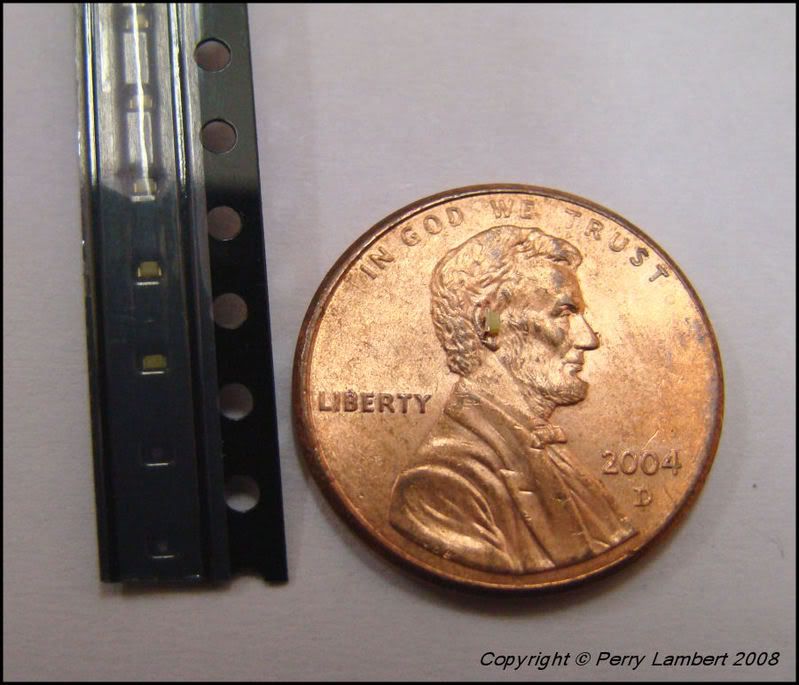 These require Optivisors and a needle tip to solder them but it can be done. I agree with everyone else though, such an outstanding model and the extra effort of making the beacon to scale will really put this model over the edge. Now, the 0603 LED should fit inside the DW Beacon with no problems if the 0402 is too small. Perry |
|
sd50f
Superintendent
Posts: 189
|
Post by sd50f on Jul 25, 2009 20:42:40 GMT -5
Kingbright and eLed.com also have very small LEDs that could be used for your beacon. Great looking locomotives, by the way.
Timothy Dineen
|
|
|
|
Post by Raeder on Jul 30, 2009 0:46:57 GMT -5
Hi all,
I have some Ngineering LED's on order, we'll see what they look like with a rotary beacon body over them. No new pictures yet, but we're experimenting. I ordered the yellow ones, hopefully the orange of the beacon body will tint the light the way I want.
Kevin
|
|
|
|
Post by Raeder on Aug 7, 2009 1:48:28 GMT -5
Hi all,
We have the mini LED's and the 30 ga magnet wire in hand, now all I have to do is figure out how to attach the leads to them. This'll be fun, I can tell already.
I also picked up some Stratolite castings, if we are successful with the soldering, we'll have the castings to mount them to.
Kevin
|
|
|
|
Post by Raeder on Aug 16, 2009 1:26:06 GMT -5
Hi all,
Well, I had hoped to have a photo to show my work off tonight, but it looks like that is not going to be the case. The Ngineering LED was sucessfully soldered to some wires and lit up like it should, then I installed in in the beacon body and worked the base on. After that I worked out the install on the TEBUC6 roof, and modified the front wall to route the wires.
Somewhere in all the reworking of the wiring, I must have damaged the LED. I'm not sure how, or when, or where it is damaged. I glued it to the inside of the beacon body with enough glue that it shouldn't have moved any, and I thought I was careful enough drilling out the base for the wires.
I guess not.
So now I have to extract the LED from the beacon and re-do the install. Not too hard, but getting that LED out of all that CA is gonna be a problem.
We have progress of a sort, but no photos for now.
Kevin
|
|
|
|
Post by danraitz on Aug 16, 2009 8:11:15 GMT -5
but getting that LED out of all that CA is gonna be a problem. Kevin I've learned from bitter experience not to use CA to glue in light-bulbs/LED's. Now to secure them I use MicroScales "Crystal Clear". |
|
|
|
Post by mrlfan on Aug 16, 2009 12:35:50 GMT -5
Boy do I know about the agony of using CA on lights. I will have to try that crystal clear next. Glenn
|
|
|
|
Post by Raeder on Aug 22, 2009 8:39:50 GMT -5
Hi all,
Well, a little more work and we have figured out how to solder wires to LED's. Not only that, but I can do it and still have them work when the install is finished.
I soldered up and installed some surface mount white LED's into some ditch light castings from Athearn and only destroyed two of the LED's before I figured things out!
First of all, use that Ngineering 38 gauge magnet wire. Much more flexible, and works really well for this sort of thing.
Second, put the LED's on a loop of tape on work bench. This will keep them still, more or less. Tin the magnet wire, and then tin the LED pads. Here's the fun part!
Take a heavy file or some other fairly solid, thing heavy object and use it to pin the LED to the tape. This way the surface tension of the liquefied solder won't "glue" your LED to the tip of the iron.
Don't actually touch the LED with the iron. Set the iron tip on the tape near the LED, but not touching it. Bridge the gap between the LED and the iron with the solder. When it melts, some solder will flow on the iron, and some will flow onto the LED pad. Let the LED cool.
Take your pretinned 38 ga wire and set the tinned part over the pad, touch both pad and wire with the iron for a second or two, and the solder should re-melt and at that point, pull the iron, let the joint cool, and you are set.
Before going any further, test the LED to make sure it didn't get cooked. These LED's can't take heat for more than a few seconds before they are toast, but they should be able to handle getting soldered with a Radio Shack iron.
I have progress, of a sort. I still have to dig the LED out of the Stratolite casting, but now I've got a clue why it might have failed. More pictures will be posted when I have progress to report on the units. For now, I'm just upgrading my skills.
Kevin
|
|