Post by sp9003 on Apr 25, 2023 12:27:37 GMT -5
Ok, so lets try this.
I hope I'm doing that img business right...
really was made of - thank you again for finally solving that puzzle -
I figured I might have a try in a writeup of its rebuild, maybe this
will be useful for someone.
Originally (lightly) detailed and painted in 1991, I took it in for
installation of a light package in 2016 - the part of any build I
somehow enjoy the least, although its result usually add the maximum
glamour. Now having an SP C415 in the state of need of light show as
well, i figured why not combine the pain and do them together.
So we go. Here's the beauty out of hibernation:

7 years of storage under less than optimal conditions (living in a
damp and foggy neighborhood) caused quite some damage... serious
corrosion where the foam made contact, and tarnish below the decals
(from the setting solution?).

Despite the rotten paint (and corroded metal underneath) caused by
humidity and bad foam, the drive needs an upgrade (very noisy and
slow, but better than most other old KMTs I have seen), and most of
all the center radiator intake section needs some thought. After that
its the more usual work around the grabs and handrails as well lots of
plumbing around the fuel tank. Oh, and the light show...
The prototype had square-corrugated stamped grid panels screwed on
from the outside, giving a pronounced relief and adding a lot to the
character of these engines. The model, however is only very thinly
surface etched. Lining it in black helped with the impression, somewhat.
Since fixing this will be the biggest (and most exciting) challenge, I'll go
for that first.
So, the largest panel on the model is 16mm wide, counting the
corrugations on prototype images gives something of 32 and 36
corrugations (I have no really clear and close photo of this, just
from publications and websites - Ryan's being the clearest - plus all
photographers focused on the cab - obviously).
There's your rivet counting on modern diesels.
Now that gives a pitch of about roughly 0.3 - 0.5mm or grooves
0.15 - 0.25mm wide. Forget mesh and "see-through" at those
dimensions. Besides, no picture of the prototype has any impression ofshowing anything behind the panels, all but structured soot in that
area. So it gots to be solid. Also from these pictures I'd
guesstimate the panels were about 2" thick, or 0.6mm. The hood is
from 0.5mm brass so carving these panels from brass sheet inserted
from the back is really the only way i see to do the trick. Of course
the real challenge will be painting all this...
The finest grooving tool i have is a 10 thou slitting saw, meaning a
0.24mm groove, giving a 0.5mm pitch of the corrugation. That is, 32
grooves for the wide panels, and 5 grooves for the narrow ones just
fit. The little dynamic brake intakes take 8. That should be close enough.
So much the theory.
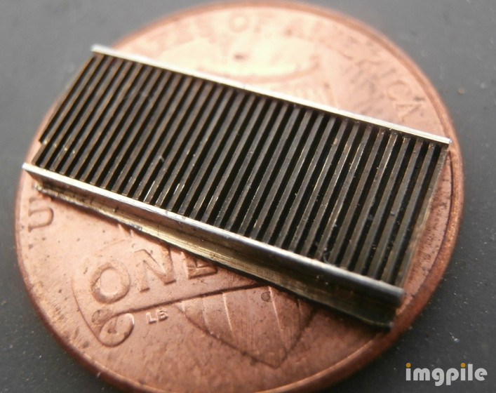
To make these panels, pieces of 1/16" brass were screwed to a squared
piece of aluminum, and the height of the panels milled at 1.1mm deep
for the retainers from the back, then orthogonal to that the grooves
cut 0.5mm deep, one by one. Having the retainers on top and bottom
should guarantee clean ends across the corrugations. Here is one of
these sheets in process:

The individual panels, then, are cut out by hand with the piercing saw
and finished with fine files. That's the result. It took 3 sheets to
produce whats needed for 1 side:

Next they need to be fitted. For that i unsoldered the radiator
section from the shell (one side only, first) and the panels are sawnout and fitted one by one as good as my eyes allow - the inserts
numbered since they all are very slightly different.
Try fit of the first one to prove the concept and see the difference,
yes, starting to look U50C to me now.

On for the rest.... All of the panels cut out, fitted and held in
place with tape to see if this is going the right way.

Thats the state of it right now. Next is to find a practical way to represent
the frames and solder the whole lot in.
thanks for listening, -m