Post by superfleet93 on Jul 12, 2008 13:43:42 GMT -5
This question was asked on another forum and I felt it could be utilized here as well. For those of you so inclined and who are building all of the piping below the sidesill, I felt these pictures would be a great help. These photos were taken of WAMX 4036 which is a GP40. I will explain where everything goes as best as I can.
Photo 1 shows the air hose arrangement on the pilot. This is located on the engineer side rear. All of these photos will walk towards the front. Above the air hoses, #1 is for the main reservoir, #2 is the actuating (blow off), #3 is the independent for the locomotive brakes.
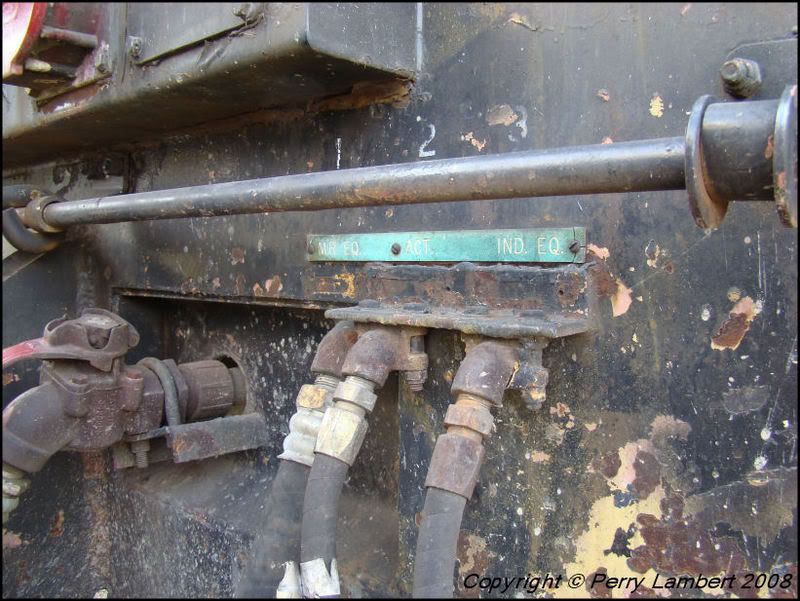
Photo 2 shows the valves on the backside of the pilot. These are manually turned on and off for multiple unit capabilities.
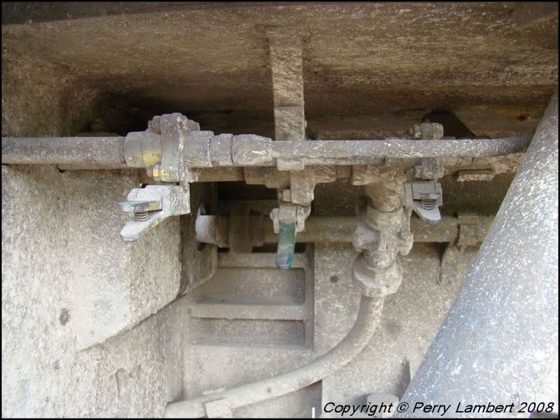
Photo 3 shows the main reservoir line hooked into the train brake line and bent at a 90 degree angle and travel beneath the draft gear. It also shows the connection for the main train brake. The middle line (actuating) is also connected to the other side then routed towards the front. The independent line is also routed towards the front and also seen is the connection from the engineer side.
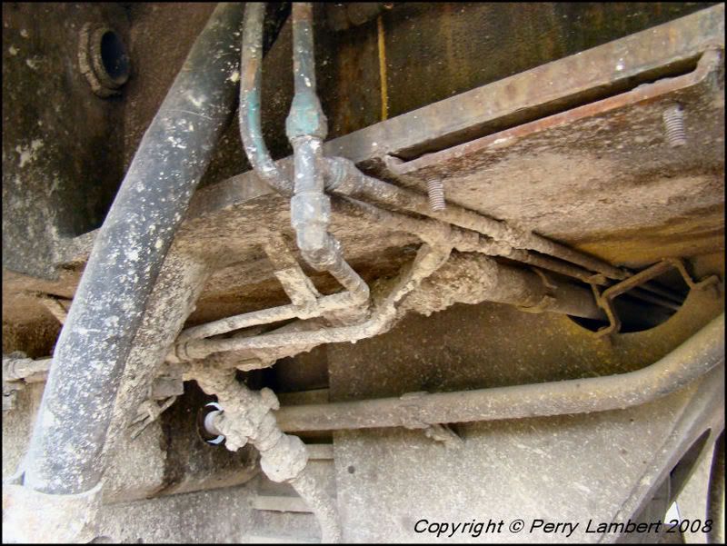
Photo 4 shows how the actuating and independent lines wrap around the I-beam frame then move towards the front. Also, these are all routed straight through from front to back on the engineer side. They only pass on the conductors side to the engineer's side.
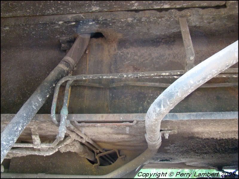
Photo 5 shows them traveling above the engineer's side rear truck. There is a pillow block every so often to keep them straight. This one is about centered with the inside brake shoe on the rear of the truck.
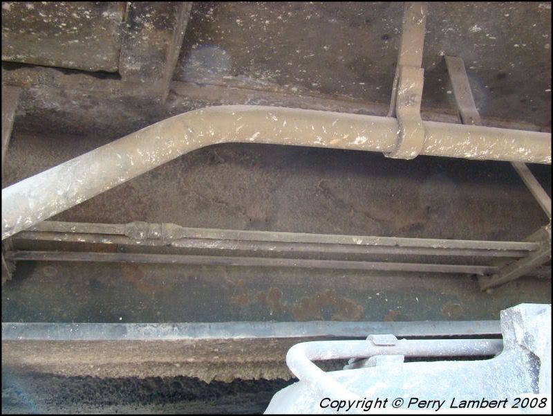
Photo 6 shows more detail of the pillow block and bracket assembly.
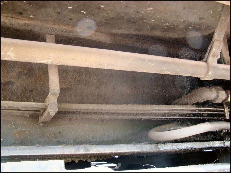
Photo 7 shows the actuating and independent lines running through the bolster extensions. The third line closest to the frame is the sander air line, so don't get that confused with the main reservoir because it looks the same.
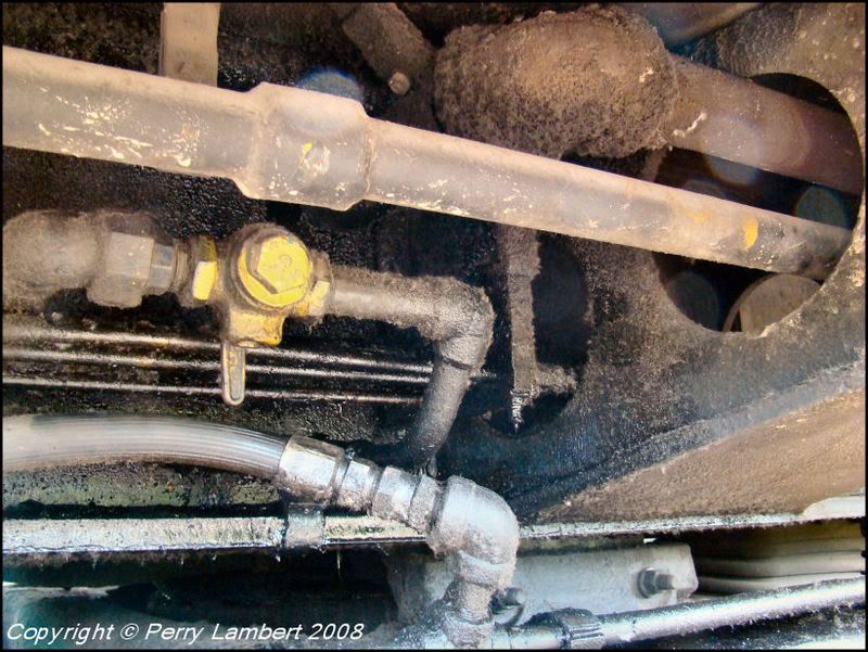
Photo 8 shows the other side of the bolster extension, closer to the rear of the fuel tank.
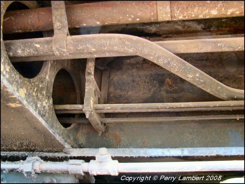
Photo 9 shows another pillow block and this one is closer to the fuel tank. It is almost centered with the other inside brake shoe.
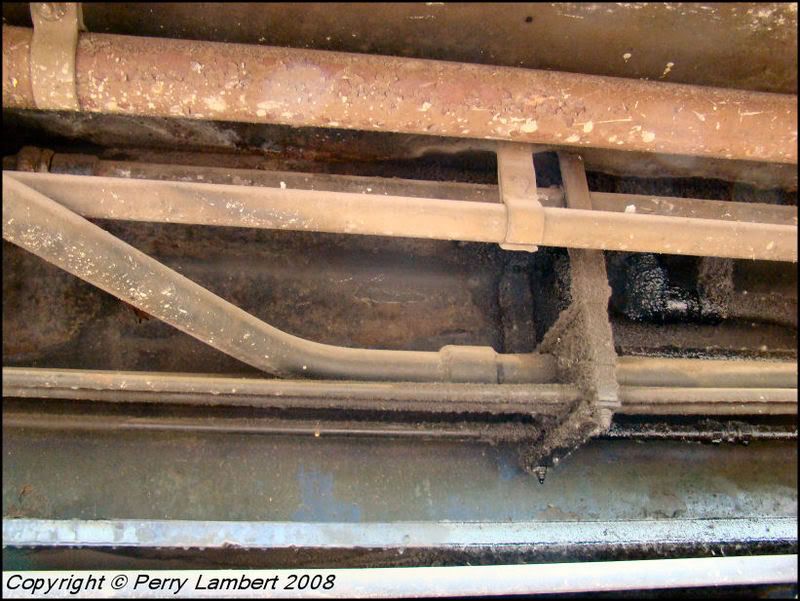
Photo 10 shows the actuating and independent through another pillow block which is just in front of the rear truck.
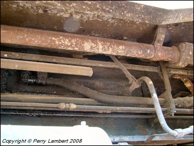
Photo 11 shows the actuating and independent running behind the rear of the air tank.
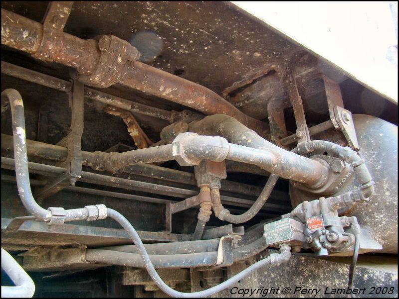
Photo 12 shows them coming out behind the front of the air tank.
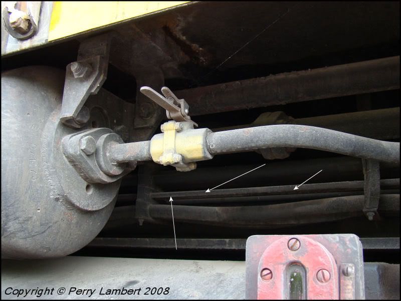
Photo 13 shows them behind the fuel fillers on the front of the fuel tank.
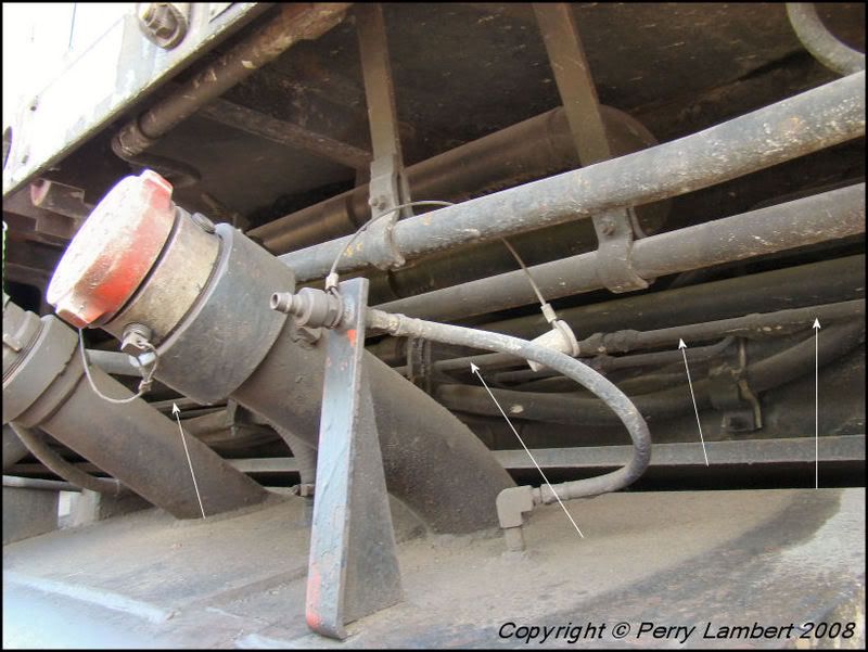
Photo 14 shows the independent and actuating into two more pillow blocks in front of the air tank.
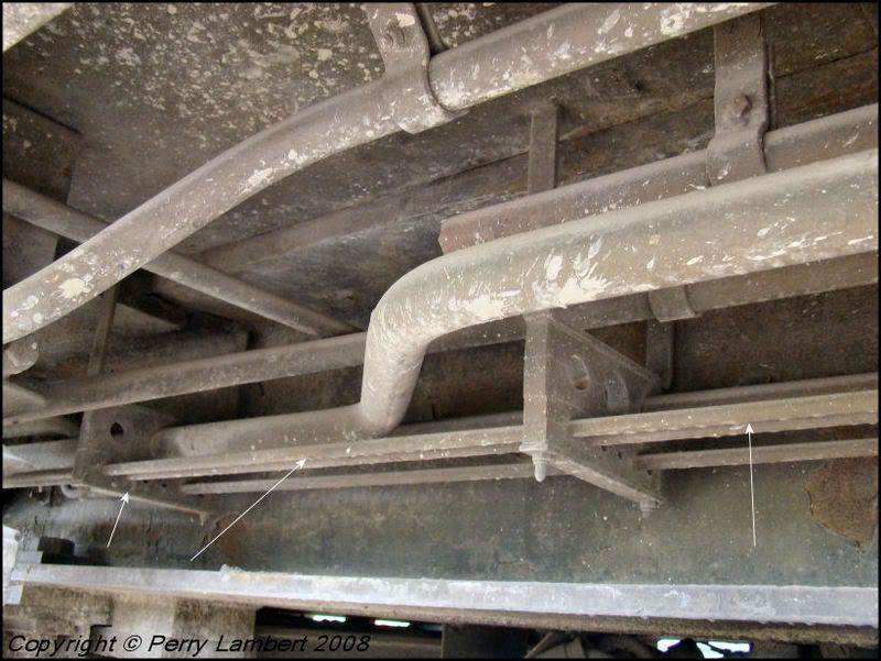
Photo 15 shows them in another pillow block just above the front truck.
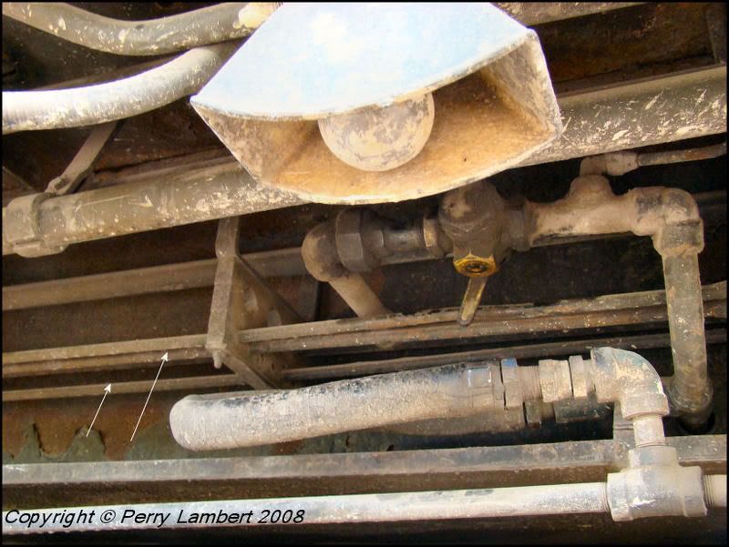
Photo 16 shows them running throught the front bolster extension.
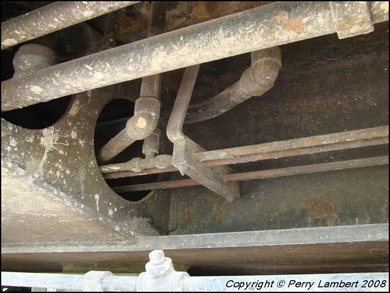
Photo 17 shows them through the pillow block and bracket, centered just above the front inside brake shoe.
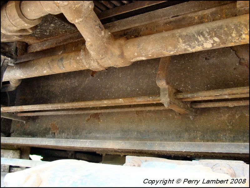
Photo 18 shows them just beneath the battery boxes.
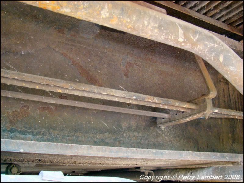
Photo 19 shows them at the front pilot and connected beneath the draft gear. Note the sander line which runs up into the floor.
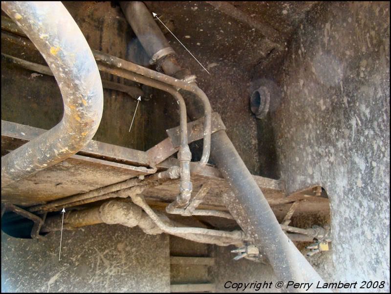
Photo 20 shows the arrangement on the front pilot, conductor's side.
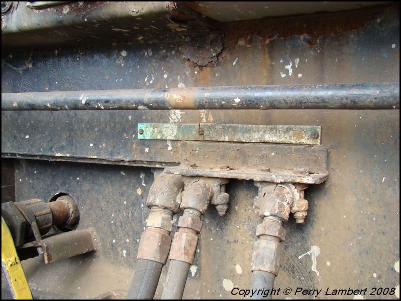
Photo 21 shows the valves on the back side of the pilot.
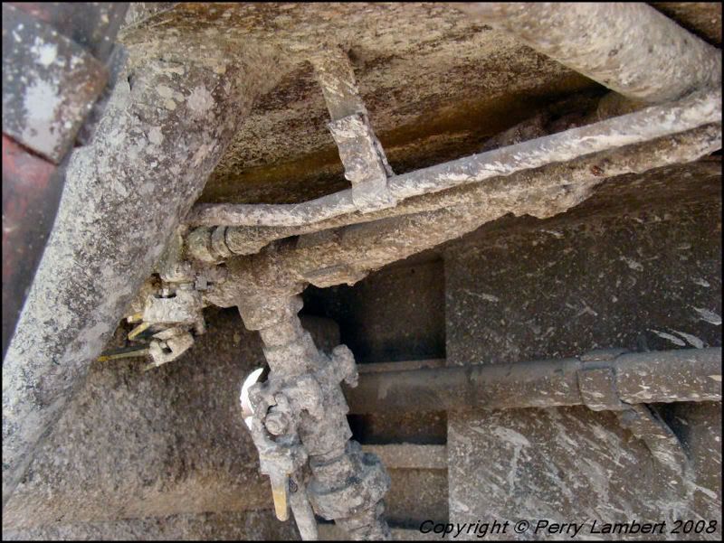
Photo 22 shows the main reservoir, actuating, and independent lines running to the engineer side. These lines all pass over.
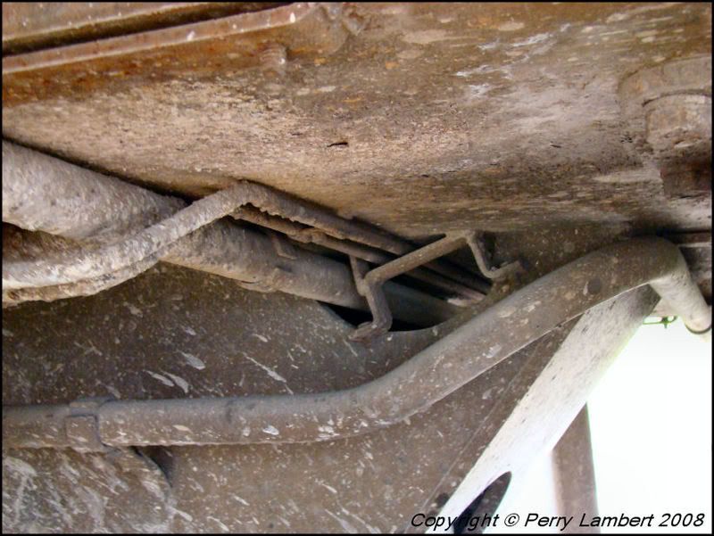
Photo 23 shows them on the conductor's side rear pilot, crossing over to the engineer's side.
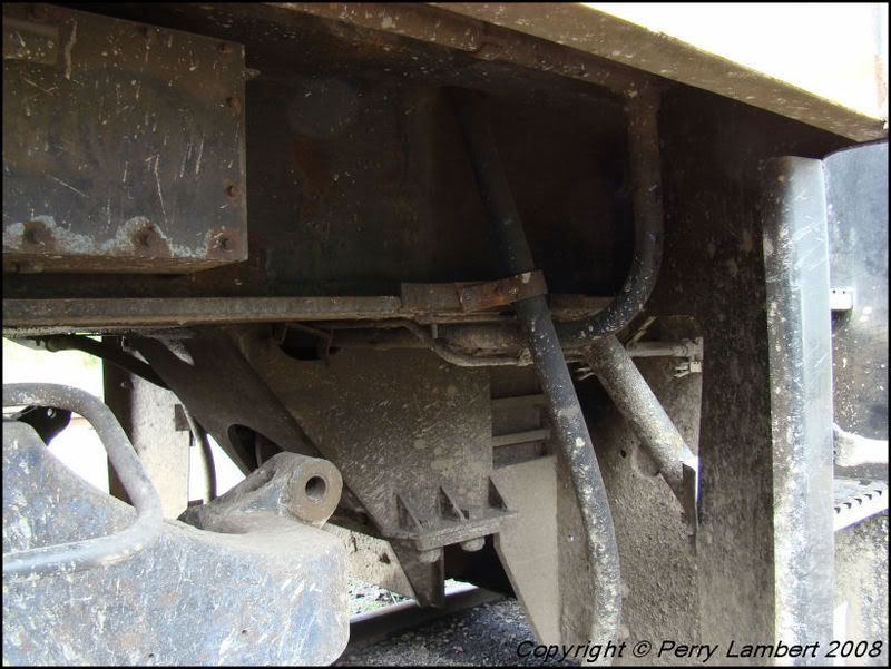
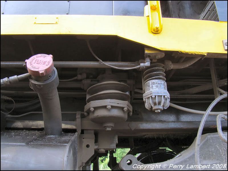
Photo 24 shows the Salem air filter arrangement, these taken on WAMX 4009, a GP40-2W.
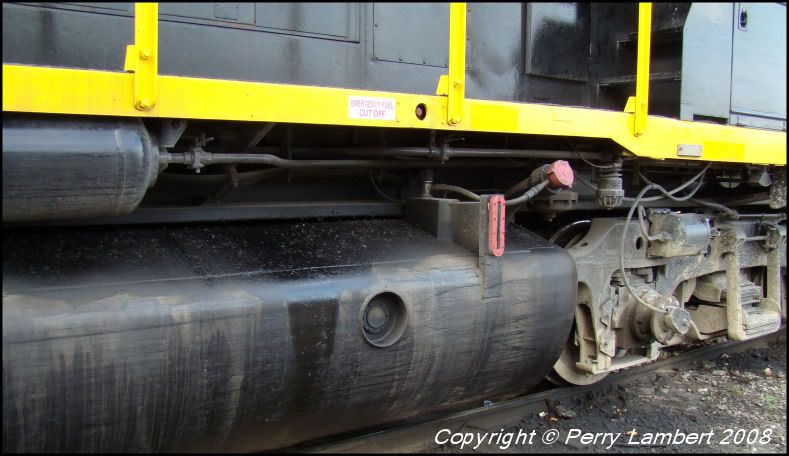
Photo 25 is a closeup of the air filter arrangement.
I hope you all can find this information helpful.
Perry
Photo 1 shows the air hose arrangement on the pilot. This is located on the engineer side rear. All of these photos will walk towards the front. Above the air hoses, #1 is for the main reservoir, #2 is the actuating (blow off), #3 is the independent for the locomotive brakes.
Photo 2 shows the valves on the backside of the pilot. These are manually turned on and off for multiple unit capabilities.
Photo 3 shows the main reservoir line hooked into the train brake line and bent at a 90 degree angle and travel beneath the draft gear. It also shows the connection for the main train brake. The middle line (actuating) is also connected to the other side then routed towards the front. The independent line is also routed towards the front and also seen is the connection from the engineer side.
Photo 4 shows how the actuating and independent lines wrap around the I-beam frame then move towards the front. Also, these are all routed straight through from front to back on the engineer side. They only pass on the conductors side to the engineer's side.
Photo 5 shows them traveling above the engineer's side rear truck. There is a pillow block every so often to keep them straight. This one is about centered with the inside brake shoe on the rear of the truck.
Photo 6 shows more detail of the pillow block and bracket assembly.
Photo 7 shows the actuating and independent lines running through the bolster extensions. The third line closest to the frame is the sander air line, so don't get that confused with the main reservoir because it looks the same.
Photo 8 shows the other side of the bolster extension, closer to the rear of the fuel tank.
Photo 9 shows another pillow block and this one is closer to the fuel tank. It is almost centered with the other inside brake shoe.
Photo 10 shows the actuating and independent through another pillow block which is just in front of the rear truck.
Photo 11 shows the actuating and independent running behind the rear of the air tank.
Photo 12 shows them coming out behind the front of the air tank.
Photo 13 shows them behind the fuel fillers on the front of the fuel tank.
Photo 14 shows the independent and actuating into two more pillow blocks in front of the air tank.
Photo 15 shows them in another pillow block just above the front truck.
Photo 16 shows them running throught the front bolster extension.
Photo 17 shows them through the pillow block and bracket, centered just above the front inside brake shoe.
Photo 18 shows them just beneath the battery boxes.
Photo 19 shows them at the front pilot and connected beneath the draft gear. Note the sander line which runs up into the floor.
Photo 20 shows the arrangement on the front pilot, conductor's side.
Photo 21 shows the valves on the back side of the pilot.
Photo 22 shows the main reservoir, actuating, and independent lines running to the engineer side. These lines all pass over.
Photo 23 shows them on the conductor's side rear pilot, crossing over to the engineer's side.
Photo 24 shows the Salem air filter arrangement, these taken on WAMX 4009, a GP40-2W.
Photo 25 is a closeup of the air filter arrangement.
I hope you all can find this information helpful.
Perry