Colin
Probationary Member
Posts: 16 
|
Post by Colin on Jun 18, 2013 1:45:22 GMT -5
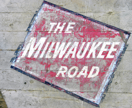
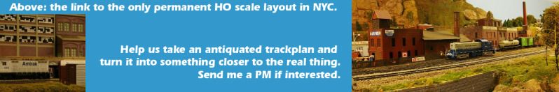
I started building my first locomotive for my future IAIS layout awhile back. I have been working on the frame details but decided to take a break and focus on the cab interior. Here is where I'm at...   My first rendition of the cab interior was a stock Cannon kit and was perfectly fine until I had the opportunity to see the prototype's cab in person (story of my modeling life!). For this, the second version, I quickly realized my Atlas worm gear and worm gear cover weren't going to allow the use of the Cannon cab floor. Wanting to add safety tread to match the prototype anyway the decision to change wasn't too difficult. 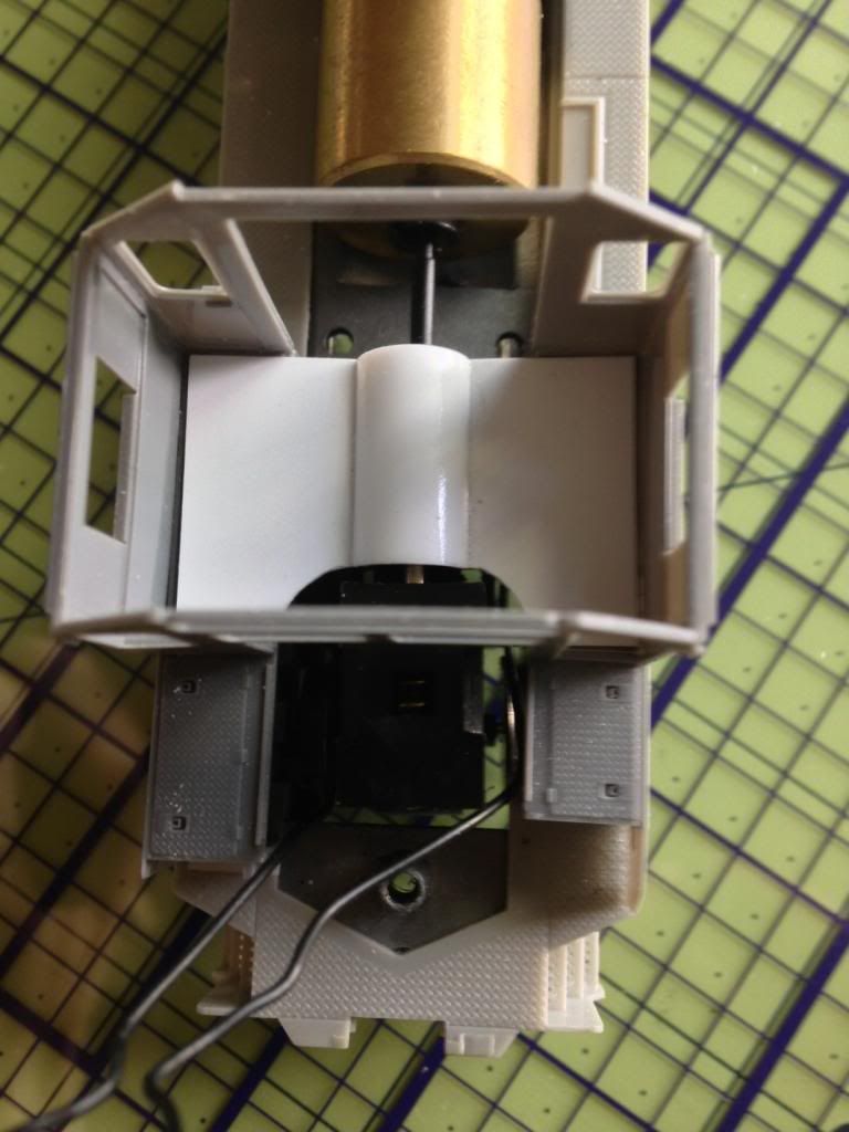 The floor started as .010" thick styrene with a cut down section of 11/32" styrene tubing down the middle to clear the drive shaft. I then cut pieces of Cannon safety tread and attached them with MEK/Barge. 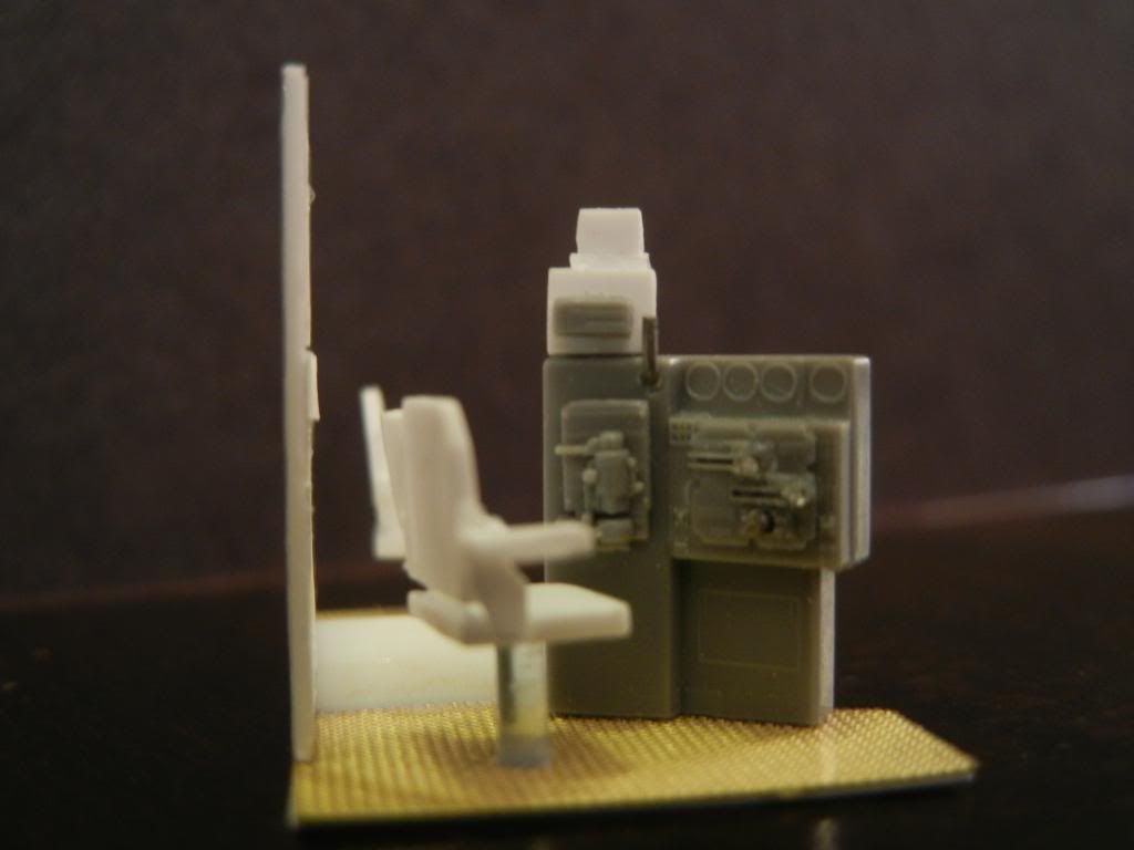 The control stand is from the Cannon cab kit. The horn, throttle, reverser and dynamic brake handles were formed from wire. I then fabricated the EOT and radio control boxes above the air brake portion of the control stand from scrap styrene, relocating the Cannon radio faceplate. I also decided I needed to update the cab seats to better reflect the more modern EMD variant. Both seats are scratchbuilt from styrene. 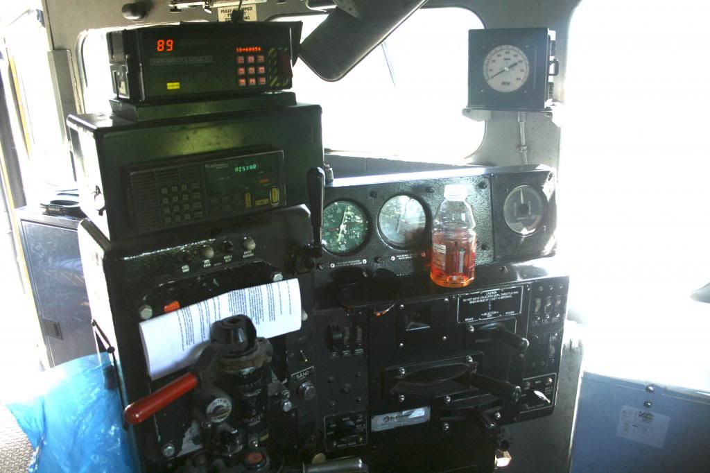 Here's a shot taken in the cab of another IAIS GP38-2 showing what I was trying to emulate on the control stand. Yes, I will be modeling the Gatorade bottle! 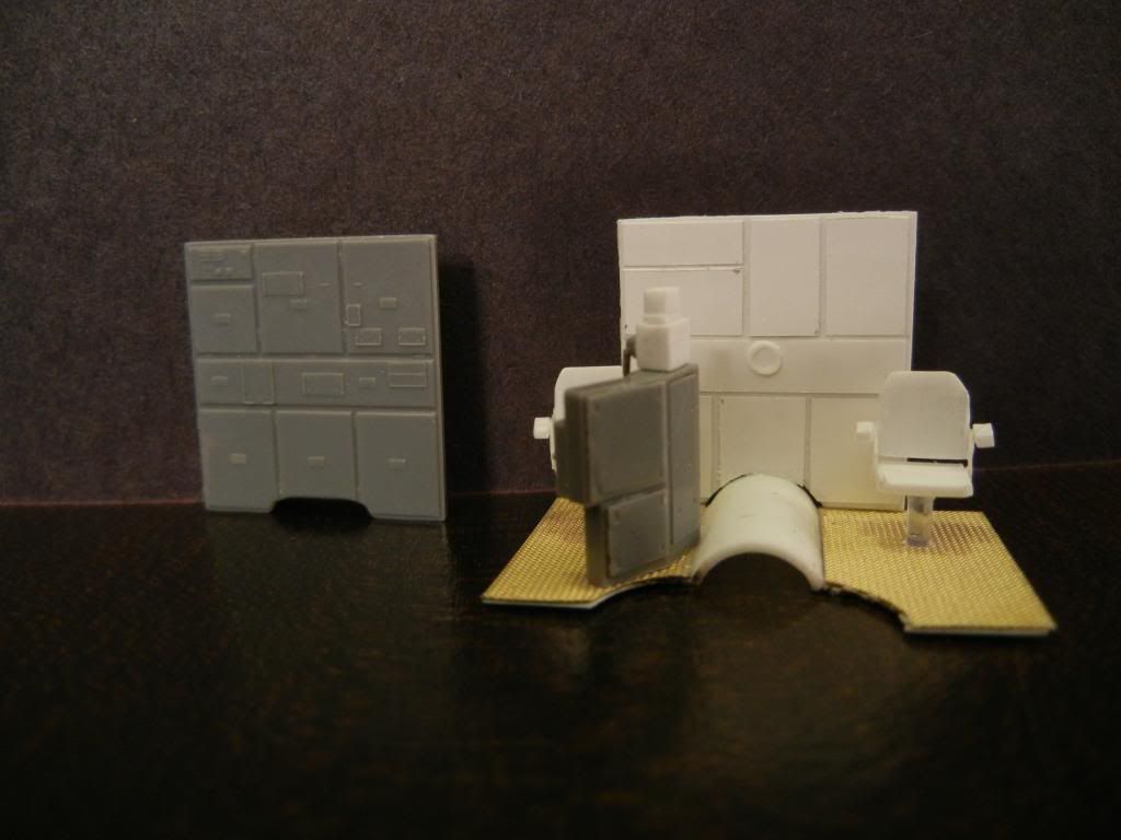 Upon closer inspection, I noticed the Cannon rear wall (see above left) didn't match the prototype (see photos below) so I decided to build a new one. I cut the new rear wall from .010” thick styrene, matching the overall dimensions to the Cannon part. 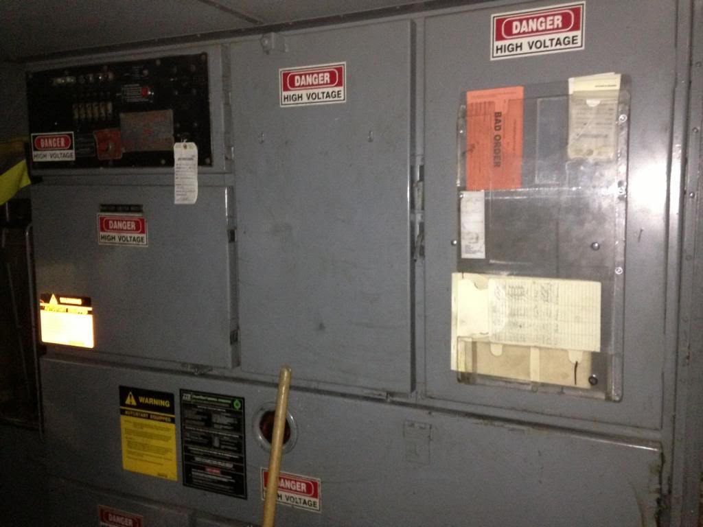 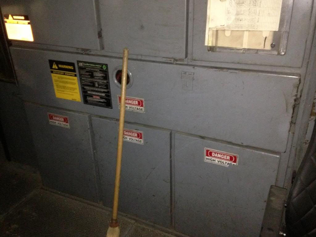 The new compartment doors were cut from .005” thick styrene to match proto photos from sister GP38-2 713 and spaced with a scale 1x2 spacer (using the 1 inch side). I added the sight glass (?) using a sliver of 3/32” styrene tubing that I cored out with #50 bit and attached with a drop of Elmer’s. 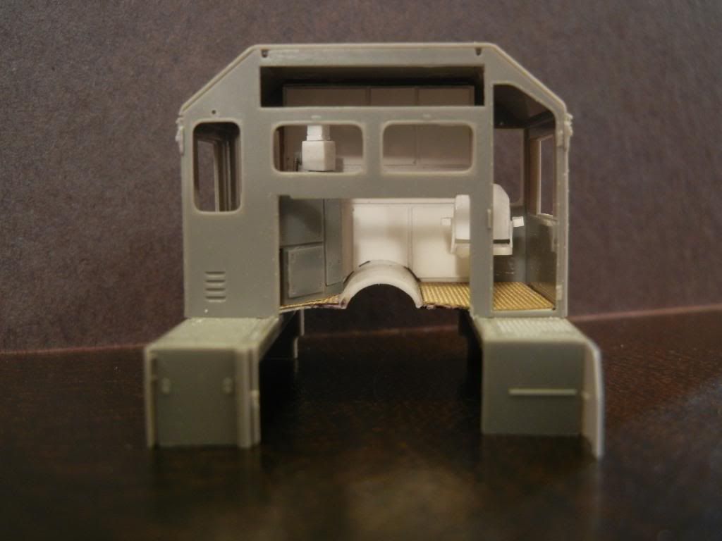 I still need to add the cab heater, speedometer, ice box, jump seat and front wall before I can call the cab interior 100% complete but I am close. -Colin |
|
|
|
Post by tamaman on Jun 18, 2013 9:36:47 GMT -5
Great start!
|
|
EMDX6043
Chairman
Future ex-modeler
Posts: 837
|
Post by EMDX6043 on Jun 18, 2013 11:53:16 GMT -5
WOW!
|
|
|
|
Post by jeff323 on Jun 18, 2013 15:20:16 GMT -5
Very impressive!
|
|
|
|
Post by Frédéric Bégin on Jun 19, 2013 0:45:29 GMT -5
Nice job indeed !
But it look like you're engine is in full dynamic brake. You got a AAR control stand installed with a separate DB handle, the upper lever. In normal operation the DB lever is fully left, hence no dynamic brake applied. On you're prototype picture however, it is one of first generation controller (EMD made two different type of selector) with a ratchet selector to choose if either the trottle lever control the trottlle or the DB brake (top right handle)
Nevertheless, pretty impressive.
Frederic
|
|
Colin
Probationary Member
Posts: 16
|
Post by Colin on Jun 19, 2013 1:42:09 GMT -5
...But it look like you're engine is in full dynamic brake. You got a AAR control stand installed with a separate DB handle, the upper lever. It appears you are correct Frederic! I had been wondering about the differences between the Cannon control stand and the one used on my prototype and you have solved the mystery, thanks! For future modeling purposes, are you aware of anyone who offers the correct control stand for my prototype? -Colin |
|
|
|
Post by icghogger on Jun 20, 2013 19:19:49 GMT -5
That kicks butt, Colin, Very Nice indeed!!
|
|
Colin
Probationary Member
Posts: 16
|
Post by Colin on Jun 25, 2013 0:27:09 GMT -5
Thanks to all for the kind words of encouragement! Tonight I added the finishing touches to the cab interior... 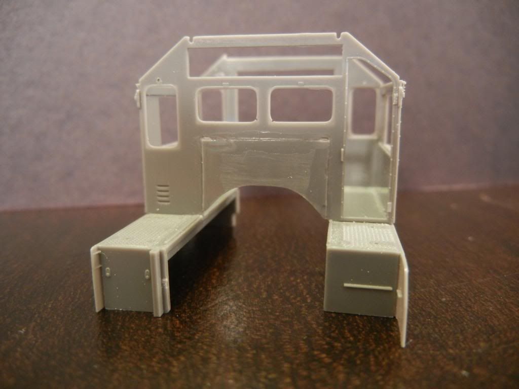 I started by cutting down the Cannon front wall to fit inside the existing opening in the cab. The arc provides clearance for the gear tower. The view from the outside looks rough but the joint will be covered up nicely when the Cannon nose is in place. 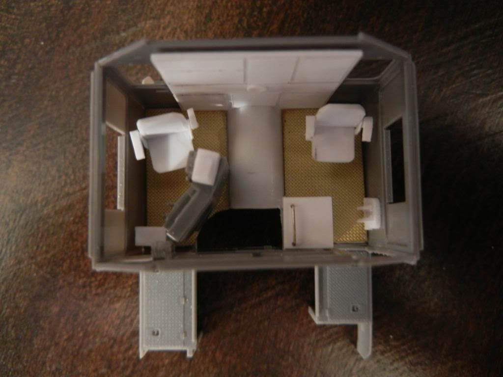 Here's the view from the top. New additions include the cab heater (white box in bottom left hand corner of cab), the speedometer (silver piece hovering above the cab heater), the ice box (white thing with grab iron on top), and the jump seat (bottom right hand corner near conductor's side window). 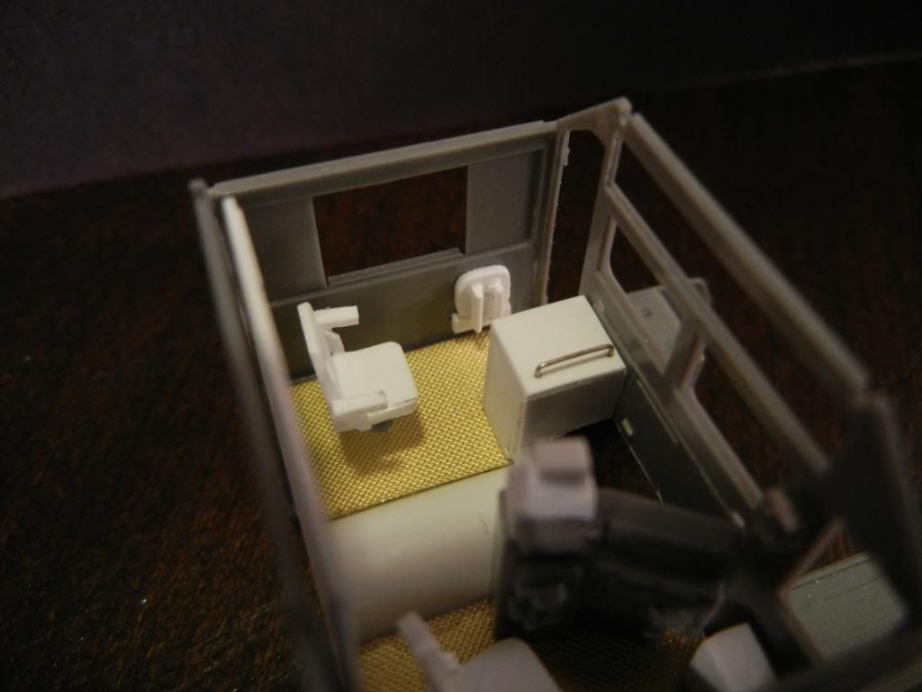 The jump seat was scratchbuilt from .030” thick styrene and 3/64” tees with one side of the tee removed (replicating angle iron). It is temporarily tacked in place for photos. The ice box was fabricated from .020” thick styrene for the sides and top and a .040” thick styrene strip at the base. I built the box with three full sides and an open back, then cut away a portion of the side below the grab iron to allow the gear tower to clear. 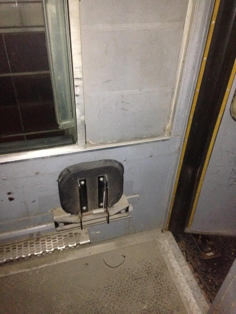 Here is the prototype's jump seat... 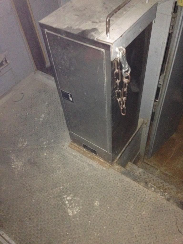 ...and ice box. 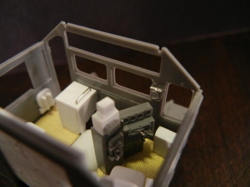 The speedometer is a filed down casting from Keystone Locomotive Works. Like the jump seat it is temporarily tacked in place for photos. After reviewing prototype photos I discovered that the Cannon cab heater wasn't a match for my prototype, thus the scrathbuilt version of that. 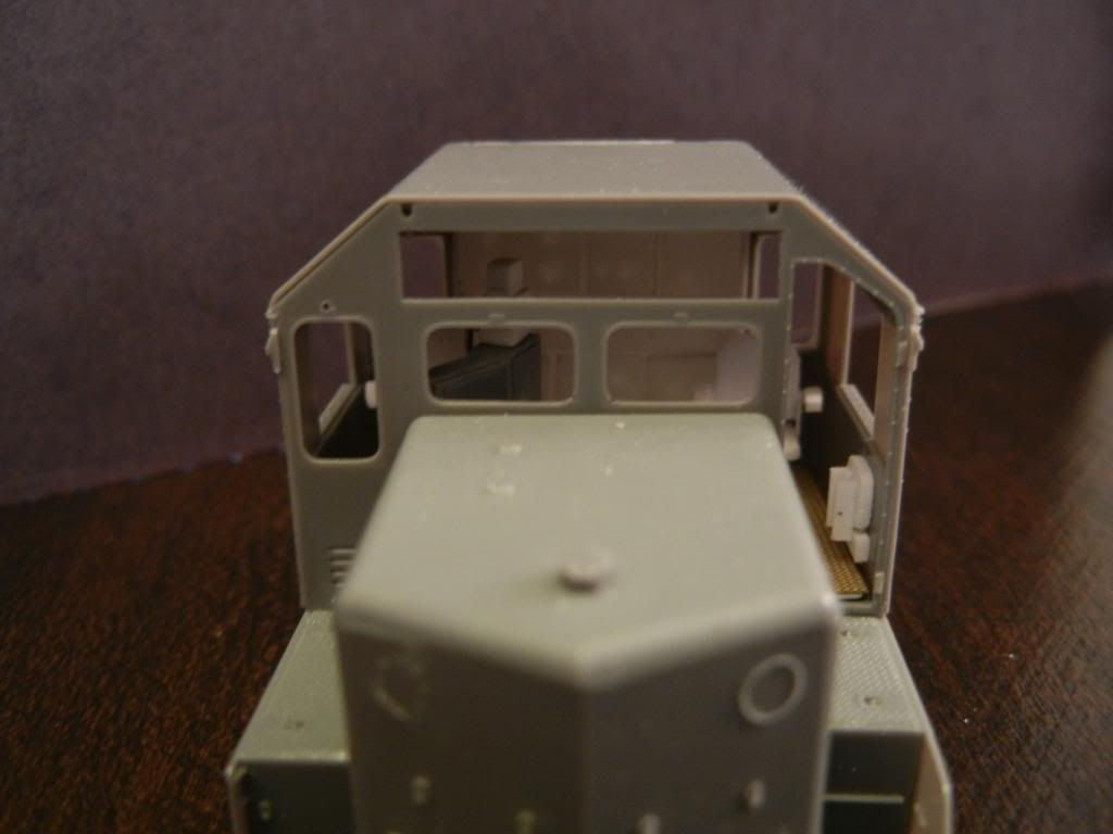 Finally, here is a shot with the nose and cab roof temporarily set in place. -Colin |
|
Deleted
Deleted Member
Posts: 0
|
Post by Deleted on Jun 25, 2013 2:18:44 GMT -5
Coming along nicely, your attention to detail is incredible. I have an eye for getting things right but your taking it to a whole new level!
Sent from my GT-I9100 using proboards
|
|
TJ
Probationary Member
Posts: 7
|
Post by TJ on Jun 25, 2013 12:22:03 GMT -5
Very Nice Colin!
|
|
Colin
Probationary Member
Posts: 16
|
Post by Colin on Jul 5, 2013 0:11:50 GMT -5
Finished my first ever "Bannadaptor" conversion tonight... 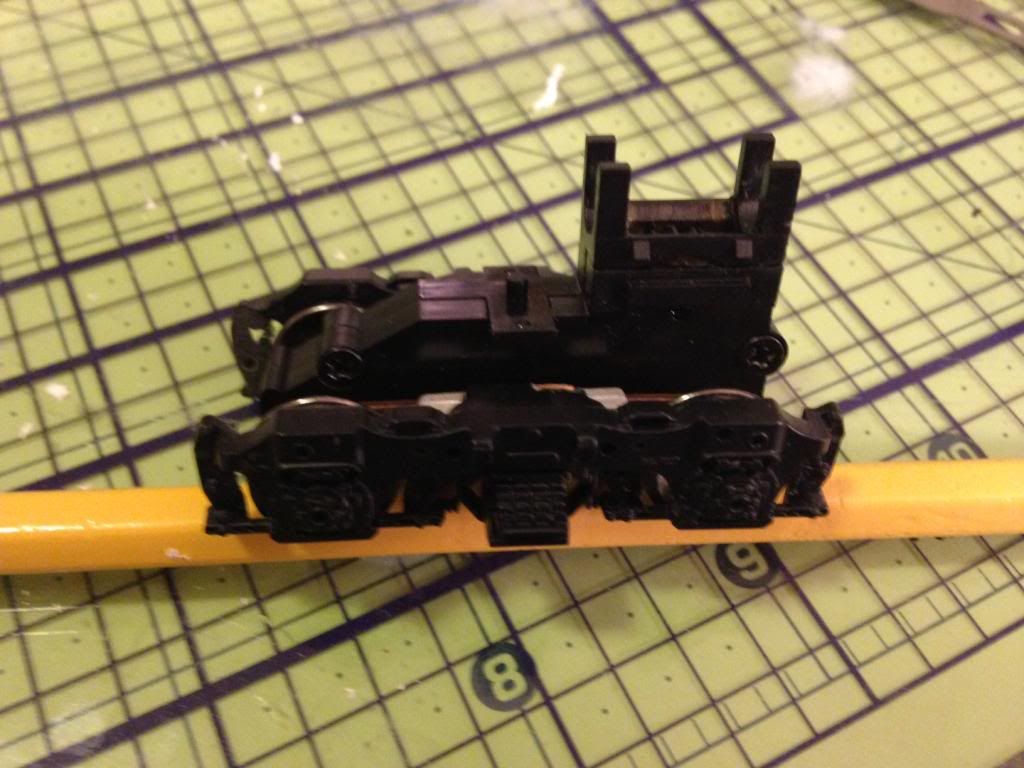 The adaptors allow the use of Athearn's highly detailed Blomberg sideframes on Atlas' gear boxes. Once both trucks are done and tested I will add all the fantastic details. A very big thanks to Brian Banna for taking the time to develop the adaptor and an even bigger thank you for creating such detailed step-by-step instructions. Your efforts are sincerely appreciated! -Colin |
|
|
|
Post by m a y o r 79 on Jul 6, 2013 11:48:37 GMT -5
Wow that cab interior is impressive!
|
|
|
|
Post by ssgburme on Jul 7, 2013 8:42:03 GMT -5
I'll get some #709 cab pictures tonight. Did you need some frame pics too?
Karl
|
|
Colin
Probationary Member
Posts: 16
|
Post by Colin on Jul 7, 2013 23:47:38 GMT -5
I'll get some #709 cab pictures tonight. Did you need some frame pics too? Karl Karl, that would be great! Thank you for offering! If you could get any shots of the sanding lines on the trucks that would be extremely helpful. In various pictures I have I can see the sanding hoses on the outside of each truck sideframe (towards the pilot) but cannot find any sign of a hose on the inside of each sideframe (towards the fuel tank). I assume that each truck has four hoses, one at each end of both sideframes, but can't verify that in prototype photos. -Colin |
|
|
|
Post by icghogger on Jul 9, 2013 13:23:12 GMT -5
Colin, most railroads removed the inside sanders 10 or 15 years ago to eliminate maintenance issues. However. there may be some still in service, but two per truck is most common.
|
|
|
|
Post by ssgburme on Jul 9, 2013 21:11:59 GMT -5
709 has clasp brakes, only the lead axle(s) has sanders. I'll look behind the sander door to see if ever had 8 wheel sanding. Most of high horsepower 4 axle motors have 8wheel sanding.
Karl
|
|
Colin
Probationary Member
Posts: 16
|
Post by Colin on Jul 9, 2013 21:31:47 GMT -5
Thanks Robert and Karl for the info regarding the sand lines!
I've almost got the trucks done and will post photos soon.
-Colin
|
|
Colin
Probationary Member
Posts: 16
|
Post by Colin on Jul 12, 2013 16:52:00 GMT -5
As promised, here are some views of the completed trucks... 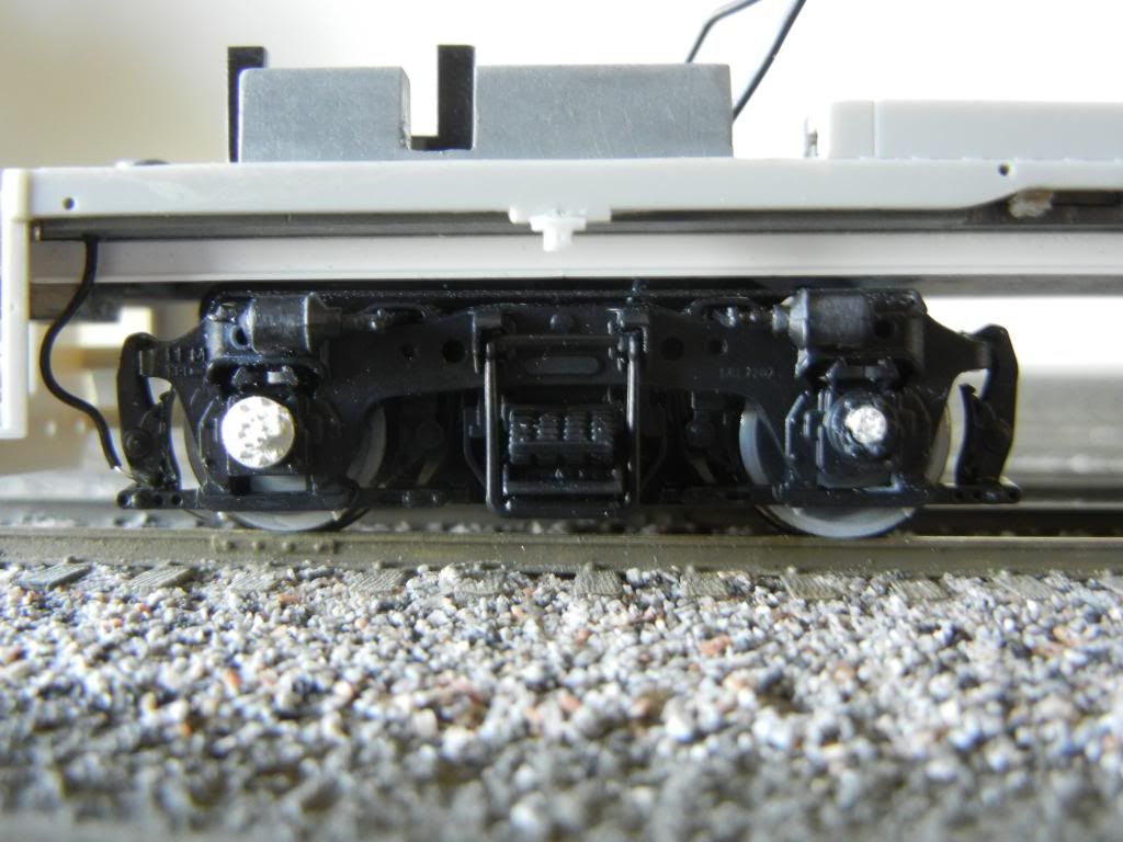 Both Atlas trucks have been retrofitted with Athearn sideframes using "Bannadaptors". Athearn's swing hangers and brake cylinders were added along with the brake pipe lines from the discarded Atlas sideframes. Detail Associates NBW castings were then added on the underside of the slack adjusters. The sideframe on the lead truck, conductor's side (pictured), also received a Details West speed recorder. What appears to be some sort of axle bearing cap (possibly leftover from another appliance attached to the axle) was modeled from a second, filed down speed recorder. The wheel faces are in gray primer in preparation for oil paint and powder weathering in the future. 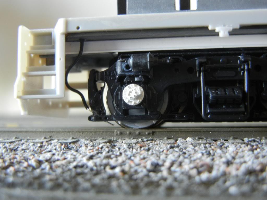 My favorite part of the truck detailing process is the sand lines, made from Miniatronics grain of wheat bulb wire. A #80 hole was drilled at an angle through the slack adjuster and then the stripped end of the wire was inserted and glued to the sideframe. A #71 hole was then drilled into the underside of the frame and the top end of the wire was inserted into the hole with a dab of Woodland Scenics Accent Glue. This allows me to take the trucks off the locomotive should I need to do any maintenance yet keeps the wire in place during normal operation. 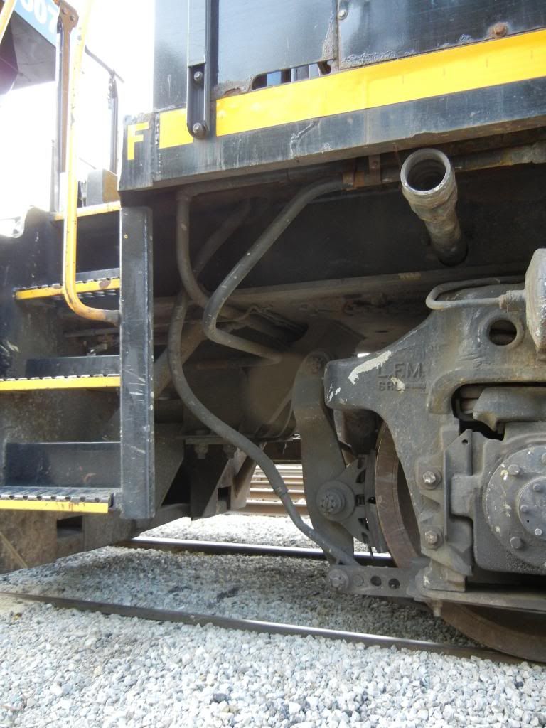 Here's a prototype view for comparison. I still need to tweak the wire a bit to better reflect the path taken by the real sand line but that is an easy fix given the pliability of the wire. -Colin |
|
|
|
Post by diesel on Jan 28, 2014 23:43:38 GMT -5
holy moly!
That is gonna be one sweet piece when it's done!
I'm assuming with all the excellent work you're putting
into this you will modify the small aspects of the step well
to match the pictures, right? -that cab is sick!
|
|
|
|
Post by stevef45 on Jan 29, 2014 2:08:02 GMT -5
you have a part number for that keystone loco works speedometer?
|
|