tingoat
Road Foreman
Ignorant Know-It-All
Posts: 55
|
Post by tingoat on Jan 21, 2013 13:21:52 GMT -5
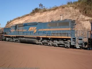
Hi Gang, I'm looking for pictures or drawings of an F7's Frame/Chassis without the cladding. I've been tinkering with a couple of old F7 shells on and off (Mostly off) for the past few years. I grafted GP7 porches onto the noses of F7 shells. I was also thinking about how to create Draper Tapers to them but my interest has shifted to modern era and gen-sets. I was thinking that the project was a dead end but... Surfing around the 'net I came across the Global Locomotive Website. In particular, the conceptual drawings of a Cab Unit rebuild.   As you see, the skin has been removed and just the Trusses remain on the sides. I imagine that this might be the way for me to create a F7 based Multi-Genset. |
|
Deleted
Deleted Member
Posts: 0
|
Post by Deleted on Jan 21, 2013 14:18:24 GMT -5
I read this on my mobile and imagined something completely different to the photo's , which, I had to look on my laptop to see. I had visions of just an F-unit with the draper taper, I can see this working better with a re-built E-unit (with just a single prime mover) and a late EMD style layout of machinery but whatever you come up with looks like it's going to be a fun build.
|
|
|
|
Post by slowfreight on Jan 22, 2013 10:04:41 GMT -5
|
|
tingoat
Road Foreman
Ignorant Know-It-All
Posts: 55
|
Post by tingoat on Jan 22, 2013 10:24:21 GMT -5
Correct me if I'm wrong, but...
While considering the feasibility of this project in terms of the prototype, I was thinking that the skin contributes to the strength of the frame. If the skin were removed, the trusses of the chassis would need to be reinforced.
Which isn't out of line with strengthening that would be required to lengthen the frame to support the porches I'm adding to them.
Also...
I did a little looking at locomotive lengths to figure out what would fit, and it looks like an F-Unit could carry two Gensets based on NRE GS14b or similar specifications.
Maybe 4 gensets would fit into an E-Unit.
If you position the gensets transversely or side by side, I suppose that 3 or 4 could be fit in an F-Unit... Something more like the Bombardier TRAXX Multi-Engine 4-Genset.
From what I've seen, Cummins and Caterpillar lead the pack with 600-700 hp self contained gensets.
Open skid mounted gensets could be fit into a Cab Unit without removing the skin...
Since this is just a fantasy Loco, I would consider something like the John Deere 60 Hz Tier 3 PowerTech ™ Plus 6135 Generator Drive Engines.
I think that 4 of these could be fit into an F-Unit for ~1600hp...
|
|
|
|
Post by slowfreight on Jan 23, 2013 18:50:15 GMT -5
Side panels did not contribute to structural strength. Bear in mind the ATSF CF7 rebuild program, which used F units as a core to produce this: www.rrpicturearchives.net/showPicture.aspx?id=678953It sounds like you're trying to build something that is less-involved....say, something that could be done in-house without serious steel fabricating capability, and would reuse the cab and bridge trusses. Chicago-area E & F units, plus Amtrak's SDP40F, all had skid-mounted Cummins (or similar) gensets for HEP, so the precedent is there for skid-mounting a diesel plant successfully. If you didn't remove the skin on a carbody unit, you'd simply remove roof sections and drop the new skids inside. This is another in-house Genset conversion, done with an SW unit that was not road-worthy and otherwise in line to be scrapped: www.flickr.com/photos/dmorg45/4808498620/in/photostreamI think it actually got brought to the shop on a flatcar because the trucks were not roller-bearing equipped. FWIW, I asked the CMO how they made sure that a frame would be good when they reused it, and he said that as long as it's in true and tram, they can tell from a visual inspection if the metallurgy is still good. So, feel free to use anything you like as a core. |
|
|
|
Post by iomalley on Jan 24, 2013 12:32:35 GMT -5
I agree with slowfreight, the skin has no bearing on structure as this photo will attest... www.cnrphotos.com/gallery2/main.php?g2_itemId=55095the sidesheets peeled away like tinfoil. The F cabs were made to snap behind the cab to reduce impact damage. The CF7 program, if you look at the photo from slowfreight, shows a very robust fabricated sidesill which replaced the warren trusses that held the F7 together. a draper taper using the F7s trusses would limit visibilty to the rear. There's a pic of GMDDs first FP7 floating around the net (with a TH&B GP7 in the background) that shows the guts well. I'll see if I can find it... |
|
tingoat
Road Foreman
Ignorant Know-It-All
Posts: 55
|
Post by tingoat on Jan 25, 2013 12:03:25 GMT -5
Hi Guys,
Thanks for the feedback.
I've been playing with M$ Paint and a couple of Traniax drawings to try and cut-n-paste what I have in mind.
Also, looking at various photos to try and get the truss arrangement sorted out.
The Global Locomotive shows a PA/FA conversion. The Trusses on the sides are only half height.
As far as I can tell, the F and E Units appear to have the Trusses all the way up to the roof line.
Either Alco and EMD had very different Truss Structures or Global has cut away the top half of the structure.
I'm thinking that Global's conceptual drawing is flawed and unless their GenSet is picking up part of the structural load, they have seriously compromised the integrity of the frame.
I have to adjust my thinking on this project once again.
I've been trying to convert a Road Engine into a Road/Switcher.
The CF7 was the ideal method for this because the Trusses have been removed. Any other way doesn't really work for achieving maximum rearward visibility.
That being said, this is the 21st century.
A GenSet Conversion for an F-Unit would take advantage of modern technology.
So, a simpler method would be the addition of remote controls and video cameras to give all round visuals.
|
|
tingoat
Road Foreman
Ignorant Know-It-All
Posts: 55
|
Post by tingoat on Jan 25, 2013 14:32:38 GMT -5
|
|
tingoat
Road Foreman
Ignorant Know-It-All
Posts: 55
|
Post by tingoat on Jan 25, 2013 20:04:14 GMT -5
|
|
|
|
Post by CP_8530 on Jan 26, 2013 3:01:17 GMT -5
... The F cabs were made to snap behind the cab to reduce impact damage.... Weeeeell, that's not entirely true. There hasn't been any EMD/GMD documents or literature that has surfaced to back this up. Methinks it's just something that happens in serious head-on incidents due to the design, but it wasn't intentional. |
|
tingoat
Road Foreman
Ignorant Know-It-All
Posts: 55
|
Post by tingoat on Jan 30, 2013 13:47:24 GMT -5
I've been mulling this project for a long time and I think that the latest iteration may be doable. I've blurbed it on my blog: Humber Valley & Simcoe Railway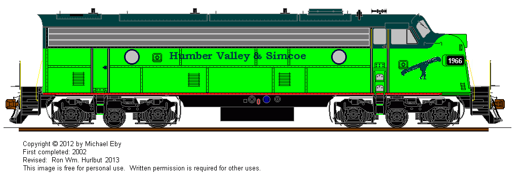 |
|
|
|
Post by spud7378 on Jan 30, 2013 15:52:15 GMT -5
I like the look it is similar to the onr paint scheme just different colors
|
|
|
|
Post by slowfreight on Jan 31, 2013 12:39:17 GMT -5
|
|
tingoat
Road Foreman
Ignorant Know-It-All
Posts: 55
|
Post by tingoat on Jan 31, 2013 14:11:17 GMT -5
I like the look it is similar to the onr paint scheme just different colors Funny you should say that... It's actually the Blue VIA livery changed to Green. I started this project years ago, before I understood the differences in how Cab and Hood engine frames are built. I'm thinking that it is a case of swapping out the Anti-Climber & Pilot as well as beefing & extending the Draft Gear. Construction would be similar to the porches on a BL2. So I'll have to close in the step wells and make them look more like BL2 porches. I've updated the drawing accordingly: 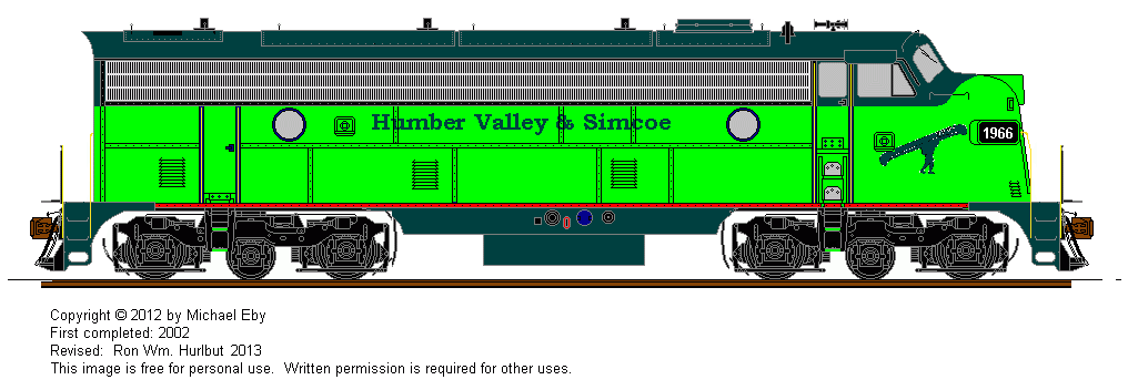 |
|